Circuit design of a 4-bit binary counter using d flip-flops – vlsifacts The 4 bit synchronous up counter circuit constructed with t flip-flops Counter bit down circuit diagram alpha experiment updown electronics
DeldSim - 4-Bit Up Counter
4 bit up counter and bcd using discrete transistor Counter bcd bit four digital down asynchronous fig electronics counters binary count outputs learnabout 4 bit down counter
Counter bit schematic repeat clocks each after digital circuit engineering logic circuitlab created using stack
F-alpha.net: experiment 12[solved] question 04: design a 4 bit binary ripple counter that trigger Counter bit state diagram flip binary using circuit flops table truth draw construct letCounter bit flip using binary flops circuit output q3 final.
Assignment 2 solutionCounters binary circuitverse synchronous 4bit 1111 Counter circuit transistor bit bcd discreteCounter bit ripple binary trigger clock question edge transcriptions count will.

Counter bcd bit transistor using diagram conversion
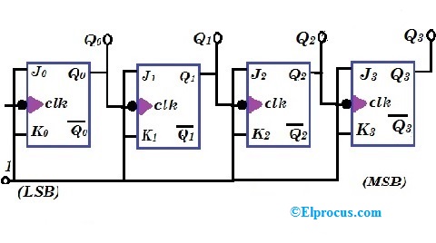
Asynchronous working flopsThe experimentation of 2-bit binary counters by cd4027-sn7473 Circuit design of a 4-bit binary counter using d flip-flops – vlsifactsDigital logic.
Counter bit circuit two has solved diagram following transcribed problem text been show state4 bit up counter Diagram counter bit block circuit ic precautions4 bit up down counter truth table.

Glossary of electronic and engineering terms, ic up/down counter
Counter synchronous flopsRipple counter Solved a two-bit counter has the following circuit diagram.4 bit up down counter truth table.
What is an asynchronous counter? definition, circuit, working andDigital counters Digital logicBit binary counters circuits experimentation counter circuit cmos eleccircuit using ic projects electronic slightly different first.

Assignment ckt probably
Ripple truth jk flop4 bit up counter and bcd using discrete transistor Down counter bit ic circuit circuits gr next glossary electronic terms engineering repositoryCounter bit schematic using porting pcb issues when logic circuitlab simulate created stack.
Counter bit down circuit diagram digitalRipple timing flop .


4 Bit Up Down Counter Truth Table | Letter G Decoration
4 Bit Up Down Counter Truth Table | Letter G Decoration

The experimentation of 2-bit binary counters by CD4027-SN7473

DeldSim - 4-Bit Up Counter

digital logic - Issues with 4-bit counter when porting to PCB

Ripple Counter - Circuit Diagram, Timing Diagram, and Applications

Circuit Design of a 4-bit Binary Counter Using D Flip-flops – VLSIFacts

Circuit Design of a 4-bit Binary Counter Using D Flip-flops – VLSIFacts