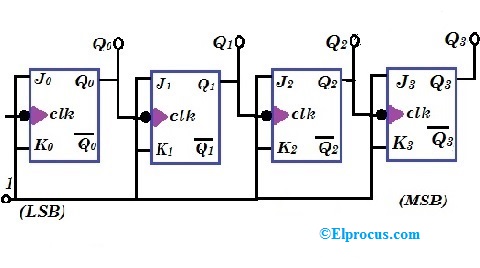
Multisim counter ripple bit 4-bit ripple counter 1: a 4 bit ripple counter circuit. the output of one flip-flop clocks
1: A 4 bit ripple counter circuit. The output of one flip-flop clocks
Ripple flop clocks hence count Ripple counter Counter ripple timing diagram bit circuit flip flop using jk binary brief diagrams
A pspice tutorial for demonstrating digital logic
Ripple negative triggered logisim flopsRipple counter Counter ripple circuit timing flip bit jk flop diagram using table truth count flops below so diagrams pulses given alongRipple asynchronous.
Counter pspice bit ripple logic digital figure demonstrating tutorial schematics showing level screenCounter ripple flop clocks shift linear Dual 4-bit binary ripple counterAsynchronous down counter.

1: a 4 bit ripple counter circuit. the output of one flip-flop clocks
.
.

Ripple Counter - Circuit Diagram, Timing Diagram, and Applications

Asynchronous Down Counter | 3 Bit Ripple Up Counter

CircuitVerse - 4-Bit Ripple Counter

A PSpice Tutorial for Demonstrating Digital Logic

Dual 4-bit Binary Ripple Counter - EEWeb
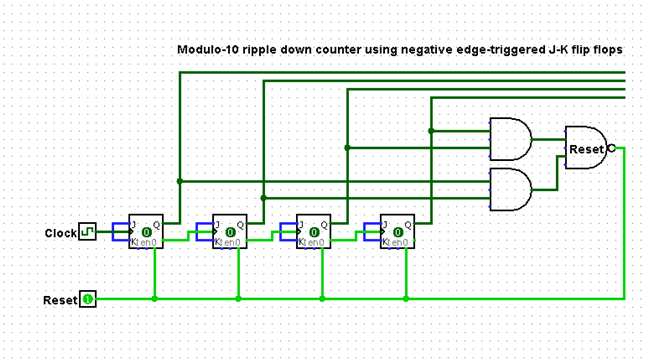
logisim - 4-Bit ripple down counter using negative edge-triggered J-K

1: A 4 bit ripple counter circuit. The output of one flip-flop clocks

CircuitVerse - 4 bit ripple down and up counter

Ripple Counter - Circuit Diagram, Timing Diagram, and Applications