Adder subtractor bit binary please electrical engineering chegg answers questions Adder half arithmetic circuits Adder binary bit addition carry python will using bits gates input combination program sign ripple
3-bit adder - CircuitLab
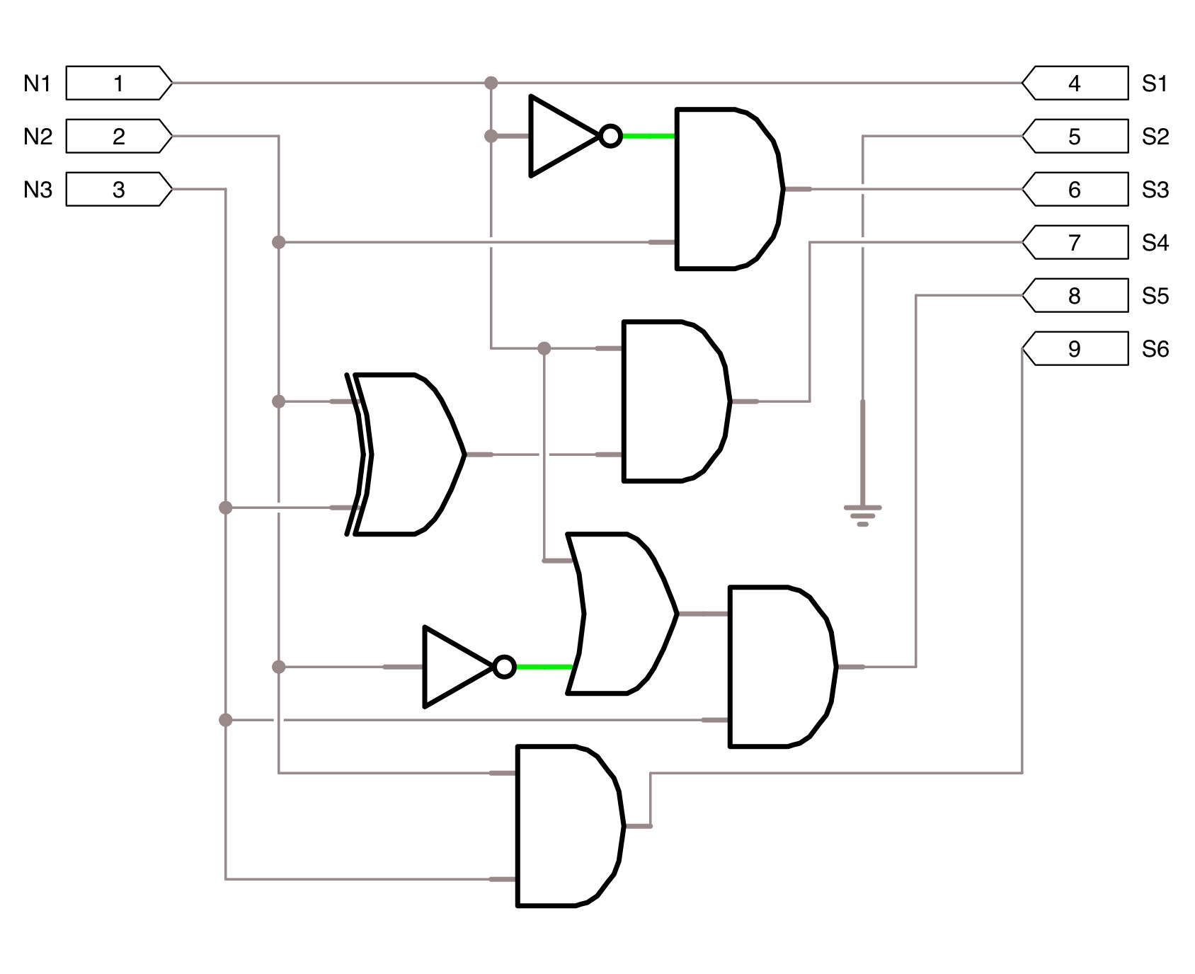
Please, design a 4-bit binary adder-subtractor. your Full adder circuit diagram A binary adder made using and-or array logic
Adder binary parallel bit logic diagram circuit electronics between
😊 four bit parallel adder. 4 bit binary adder circuit / block diagramAdder bit four diagram parallel block ripple carry circuit binary Binary adder circuit / circuit additionneur binaireAdder circuitlab.
Binary adder and binary addition using ex-or gatesLogic gates Adder bit spice youspice projects3 bit full adder.

Adder bit logic diagram combination tutor boolean gif public tutorial circuits
3 bit full adderAdder subtractor binary circuitverse Adder diagram binary additionWhat is parallel binary adder?.
Solved design a three-bit adder circuit using half-adder andBinary adder subtractor bit subtraction addition operation which value either Square 3 bit input using two 3 bit adders and logic gatesBinary arithmetic circuits.

16 bit full adder digital circuit simulation using logisim software
Adder xor rangkaian transistor ripple pengertian kombinasi3 bit adder tutorial & circuits Adder subtractor add sub bit binary logic using subtraction combinational adders circuits tutorial electronicsBinary adder/subtractor.
Design and explain 8 bit binary adder using ic 7483.Adder additionneur binaire zpag electroniques gate sum 😊 four bit parallel adder. 4 bit binary adder circuit / block diagramBit logic gates using binary input square two adders make even squarer questions stack.

Adder logisim
3-bit adderAdder logic binary circuit gates diagram using array inputs made twice labeled below also used 4-bit binary adder-subtractorAdder binary logic circuits adders implement.
Circuit diagram of a one-bit full adder using the proposed technique inAdder half circuit bit make two adders logic gates electronics combined happened has Adder bit ic 7483 using binary parallel adders four explain ques10 aheadTechnical world only.

Adder bit parallel four circuit binary diagram block example detailed discussion
Tech2play: binary additionAdder bit circuit binary schematic .
.


3 Bit Full Adder - 3 bit binary adder : Binary Options Trading Platform

4-bit binary Adder-Subtractor - GeeksforGeeks

16 bit Full Adder Digital Circuit Simulation using Logisim software

3 Bit Adder Tutorial & Circuits - Combination Logic Tutorials

Technical world Only - Circuits

A binary adder made using AND-OR array logic
square 3 bit input using two 3 bit adders and logic gates - Electrical